LC Resonant Frequency Calculator
Learn about LC resonant frequency, its formula, working, and uses. Use our LC Resonant Frequency Calculator for quick, accurate results.
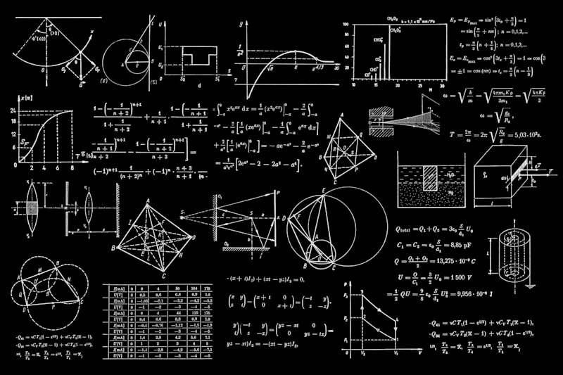
LC Resonant Circuit
LC Tank Circuit
        ┌─── L ───┐
        │         │
        │         │
        └─── C ───┘

    fr = 1/(2π√LC)
    Z0 = √(L/C)
    Q = Z0/R
Frequency Response
LC Resonant Frequency Calculator – Complete Guide
I. Introduction
The LC resonant frequency plays a central role in electronics, especially in systems where precise tuning is essential. In its simplest form, an LC circuit combines an inductor and a capacitor to determine how electrical energy oscillates at a natural frequency. This is why many engineers rely on an LC resonant frequency calculator—a convenient tool that helps estimate resonance quickly and accurately without the burden of manual calculations.

This article walks through LC circuits, explains how resonance works, covers the core formula, explores practical uses, and highlights tips for designing and troubleshooting resonant systems.
II. Understanding LC Circuits
At the heart of every LC circuit are two passive components: inductance (L) in henries and capacitance (C) in farads. When these components interact, they create energy oscillation between inductor and capacitor, forming a loop of electrical activity.

Both series LC circuit and parallel LC circuit arrangements can achieve resonance, though each behaves differently in terms of circuit impedance and current flow. This natural phenomenon is often described as resonance in electrical circuits, where reactances cancel and energy flows smoothly between the magnetic and electric fields.
III. The Resonant Frequency Formula
The foundational resonant frequency formula is:
f = 1 / (2π√(LC))
Many refer to it simply as the frequency calculation formula, and it provides the resonant frequency in Hertz (Hz). The constant π plays an essential mathematical role in shaping oscillatory behavior. For more details on resonance, visit All About Circuits.
For those exploring deeper theory, resonance frequency derivation often involves concepts like angular frequency and the transition between inductive reactance and capacitive reactance. These relationships help illustrate how electrical reactance variation defines resonance.
IV. How to Use an LC Resonant Frequency Calculator
Using a calculator is straightforward. First, enter the inductor and capacitor values, ensuring the correct units. Conversions such as microfarads to farads conversion are often necessary, especially when dealing with small components.
After processing the inputs, users can observe results in MHz, KHz frequency units, depending on application needs. Many online guides also show how to interpret frequency response curves or analyze behavior in AC circuits resonance.
A common mistake is overlooking the L and C component ratio, which directly affects tuning outcomes.
V. Practical Applications
The LC principle appears in countless systems. Designers rely on LC circuit practical applications such as RF tuning, audio shaping, and band pass filter creation. In communication systems, LC circuits for communication systems assist in selecting and rejecting frequencies. Some applications even adapt LC models as a crystal oscillator alternative. Check our Frequency Converter for related calculations.

Engineers also explore concepts like inductive coil design, coil capacitance, and the role of tank circuits in transmitters and receivers for creating stable oscillations.
VI. Factors Affecting Resonant Frequency
Real-world circuits rarely behave ideally. Elements like parasitic resistance and external influences affect performance. The Q factor (Quality factor) helps quantify how sharp the resonance is, and many measure it through a Q measurement from resonance curve.
Environmental conditions influence stability too. Temperature shifts can disturb values, altering resonance curve shape or impairing frequency accuracy. Engineers often use electrical impedance analysis to diagnose these effects.
VII. Design Considerations
Careful planning ensures the LC network performs as expected. Designers must consider capacitance selection for resonance, scalability, and component availability. They also evaluate power handling requirements and physical size constraints, especially in compact devices.
Simulations assist this process, making circuit simulation and calculation an essential part of modern design workflows.
VIII. Advanced Topics
More complex systems introduce additional behavior, such as harmonic frequency interactions and parallel and series resonance under varying loads. Engineers often compare loaded vs. unloaded Q factor values to study circuit efficiency.
Cases like surface coil resonators, coupling effects in resonant circuits, and RLC circuit resonance can dramatically alter outcome predictions. With modeling becoming increasingly powerful, computer simulation and modeling tools guide advanced experimentation.
IX. Example Calculations
1. Calculating frequency from given L and C
Assume specified inductance and capacitance are known. Plugging these into the formula immediately yields resonance.
2. Finding required capacitance
Rearranging the equation helps determine C when the intended frequency is fixed.
3. Determining inductance for a specific purpose
Engineers frequently compute L for tuning stages in RF networks.
4. Real-world case study
In many transmitter applications, designers rely on resonance frequency adjustment to fine-tune oscillators.
X. Troubleshooting and Tips
Practical experimentation always requires verification. Teams often analyze responses using step response of RLC circuits or validate with electrical oscillations observed through scopes. When discrepancies arise, adjusting components or re-measuring values helps realign target behavior.

XI. Conclusion
In summary, calculating resonance is essential for building stable and efficient circuits. Whether refining a filter, designing RF equipment, or studying LC theory through a physics tutorial on LC resonance, understanding how inductance and capacitance interact remains invaluable. Engineers are encouraged to keep experimenting and rely on accurate tools, including resonant frequency calculator online tools, to reach optimal designs.