Voltage Dividers: Theory and Practical Applications
Master voltage division principles and discover their essential role in electronic circuits and sensor interfaces
Master voltage division principles and discover their essential role in electronic circuits and sensor interfaces
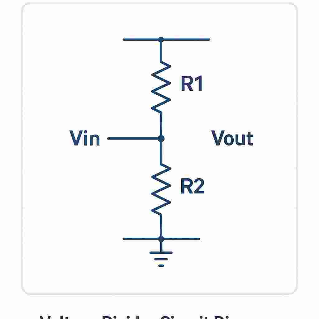
A voltage divider is one of the most fundamental circuits in electronics. It's a passive linear circuit that produces an output voltage that is a fraction of its input voltage. The circuit consists of two or more resistors in series, where the output voltage is taken from the junction between the resistors.
    Vin ──┬──── R1 ────┬──── GND
          │            │
          │            ├──── Vout
          │            │
          └──── R2 ────┘
Where:
The voltage divider works based on the principle that the voltage drop across each resistor in a series circuit is proportional to its resistance. Since the same current flows through both resistors, the voltage across each resistor follows Ohm's Law (V = I × R).
Problem: Calculate Vout when Vin = 12V, R1 = 1kΩ, R2 = 1kΩ
Solution:
Result: Equal resistors divide the voltage in half.
Problem: Calculate Vout when Vin = 9V, R1 = 2kΩ, R2 = 1kΩ
Solution:
Result: The output is 1/3 of the input voltage.
Scale down battery voltages to safe levels for microcontroller ADC inputs
Condition sensor outputs to match ADC input ranges
Potentiometers act as variable voltage dividers for audio level control
Create stable reference voltages for analog circuits
When a load is connected to the output, it acts as a parallel resistance to R2, changing the effective resistance and altering the output voltage.
Voltage dividers continuously draw current, leading to power consumption. Use higher resistance values to minimize current draw.
Resistor tolerances affect the accuracy of the output voltage. Use precision resistors for critical applications.
Temperature coefficients of resistors can cause output drift. Match temperature coefficients for stable ratios.
Adding an op-amp buffer after the voltage divider eliminates loading effects and provides a low-impedance output.
Using a potentiometer allows for variable output voltage, commonly used in volume controls and adjustable power supplies.
Multiple resistors in series can provide several different output voltages from a single input, useful in multi-rail power supplies.
Voltage dividers are fundamental building blocks in electronic circuits, offering a simple yet powerful way to scale voltages. While the basic principle is straightforward, understanding the practical considerations like loading effects, power consumption, and component tolerances is crucial for successful circuit design.
Whether you're interfacing sensors, creating reference voltages, or designing analog circuits, voltage dividers will be an essential tool in your electronics toolkit. Practice with different resistor values and always verify your calculations with simulation or measurement.